Hello, This is part 2 of my project tangletime aka “Building a time tracker using arduino and blockchain”. Where I take you along my project to build an IOT time tracker using arduino and the IOTA blockchain. If you haven’t, please consider reading the first part .
Now that the plan is laid out. It’s time to plan for the hardware. We need those components :
An arduino board, a bluetooth module, a gyroscope and lots of cables and resistors to combine all of that together.
For the arduino board, cables and resistors I bought the Freenove RFID Starter Kit V2.0 with UNO R3. It’s an awesome starter kit with basically everything you need. Then for the Bluetooth module I bought the HC 05 and the gyroscope is the MPU 6050. ultimately with a more mature product, I think I’ll go for a beetle BLE, as it’s super small, cheap and handles Bluetooth out of the box. But that’s for a later stage.
I want to make as little calculations on the board as possible to lower the power usage and to make it easier to code. The idea is simple : connect the board to the gyroscope and whenever we detect a new stable orientation. Send that orientation to via the Bluetooth module to a connected phone.
The Bluetooth module with arduino
My HC-05 was not easy to tame, I found lots of tutorials online, most of them contradicting themselves on how to wire it. The main takeaway was that if you wire it to the 0/1 port, you need to unplug those before uploading your schematics to the board.
To test things out without using the gyroscope, I quickly plugged the infrared sensor included with the freenove kit, the part name is 1838B. I like it because it’s super easy to plug (it’s like 4 jumper cables). I could go with reading serial from my computer but I figured it would be nicer this way.
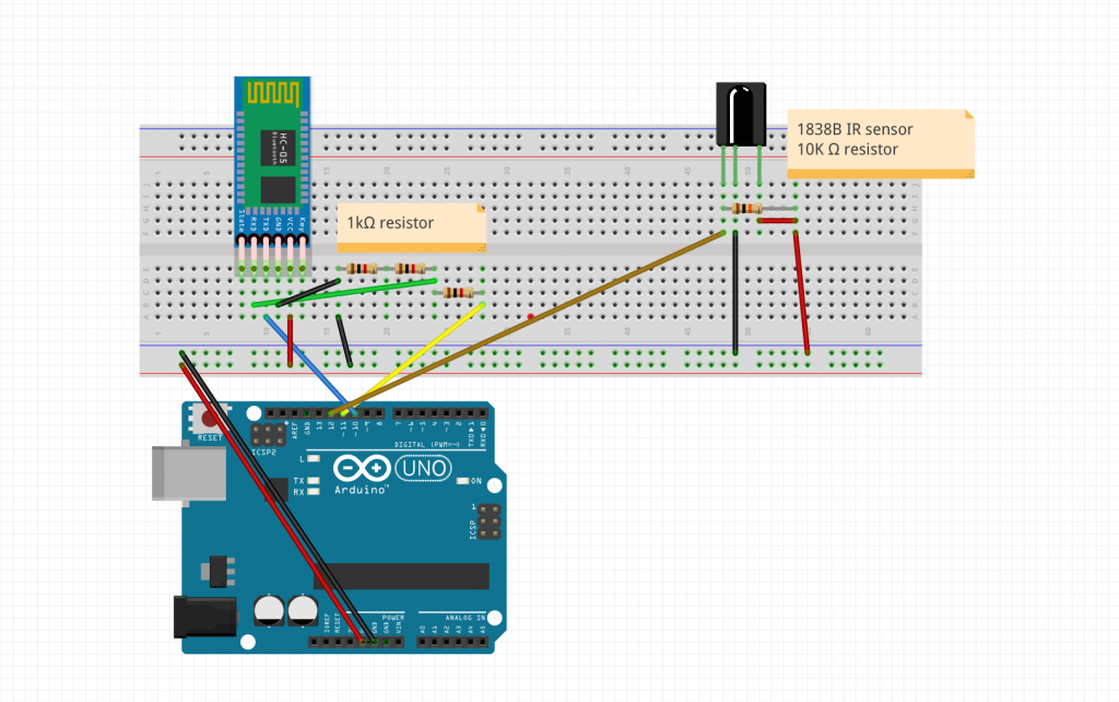
I’m sorry for the clarity of the image, but everything is there I promise.
As for the code it was pretty straightforward :
/*
IR remote keypad
0 : FF6897
1 : FF18E7
2 : FF6897
3 : FF7A85
4 : FF10EF
5 : FF38C7
6 : FF5AA5
*/
#include <IRremote.h>
#include <SoftwareSerial.h>
SoftwareSerial EEBlue(10, 11); // RX | TX
int RECV_PIN = 12; // Infrared receiving pin
IRrecv irrecv(RECV_PIN); // Create a class object used to receive class
decode_results results; // Create a decoding results class object
void setup()
{
Serial.begin(9600); // Initialize the serial port and set the baud rate to 9600
Serial.println("UNO is ready!"); // Print the string "UNO is ready!"
irrecv.enableIRIn(); // Start the receiver
EEBlue.begin(9600);
}
char value_to_char(unsigned long val)
{
if (val == 16738455)
return '0';
else if (val == 16724175)
return '1';
else if (val == 16718055)
return '2';
else if (val == 16743045)
return '3';
else if (val == 16716015)
return '4';
else if (val == 16726215)
return '5';
else if (val == 16734885)
return '6';
else if (val == 4294967295)
return 'X';
else
return '?';
}
void loop() {
// if we recieve an IR message, send it via the bluetooth module.
if (irrecv.decode(&results)) {
// Waiting for decoding
Serial.println(results.value); // Print out the decoded results
Serial.println(value_to_char(results.value)); // Print out the corresponding character
EEBlue.write(value_to_char(results.value));
irrecv.resume(); // Receive the next value
}
// Feed any data from bluetooth to Terminal.
if (EEBlue.available())
{
Serial.println(EEBlue.read());
}
// Feed all data from termial to bluetooth
if (Serial.available())
EEBlue.write(Serial.read());
delay(100);
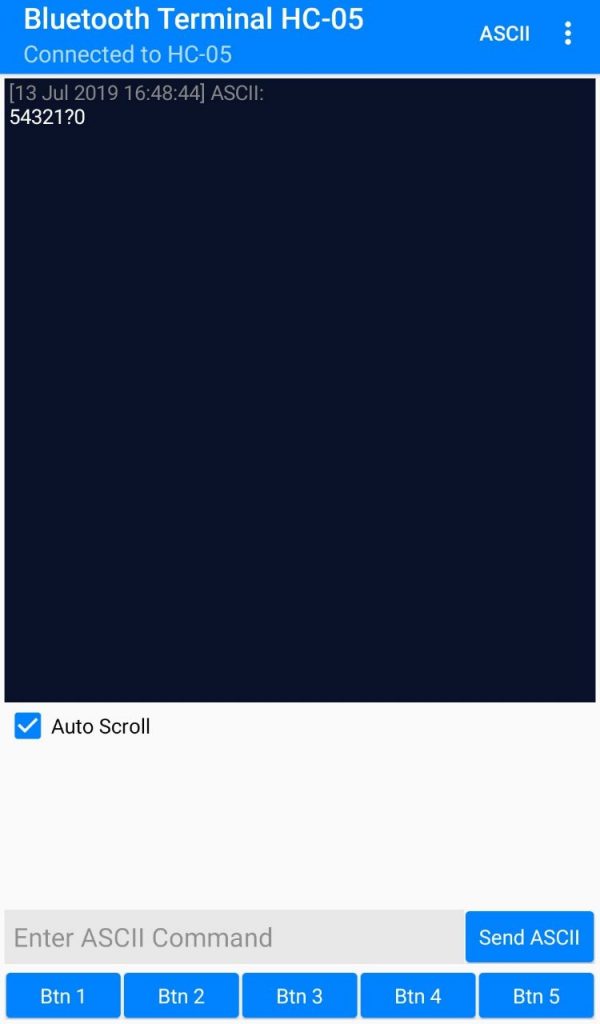
}To test everything, I used an app called “Bluetooth terminal HC-05” which basically allows you to send and receive data from the HC-05. It’s a lifesaver when you are working on the hardware side and don’t want to spend time making a quick and dirty app just to receive Bluetooth data.
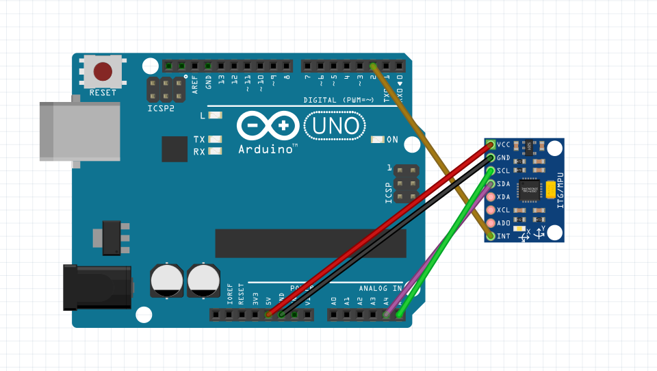
The final arduino setup
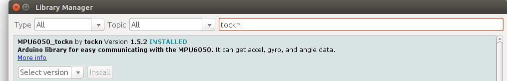
I wrote a whole article on the subject that you can find here ! So I’ll skip the details on how to set it up. And go straight to how I use it.
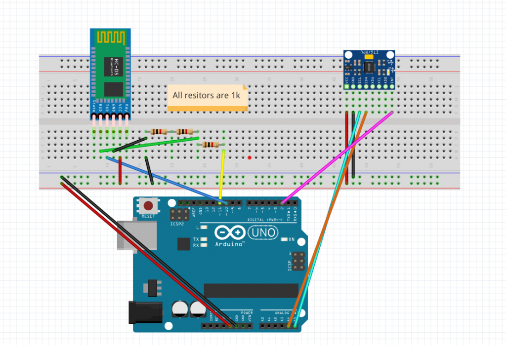
So here’s the “final” setup in terms of hardware. As for the code now all that’s left to do is to find all the x/y/z values for each side of the cube. But I don’t have a cube yet, and the arduino UNO board is way too big. So for now I’m going to make a first proof of concept where the time tracker only has two sides : register if the board is pointing left or right.
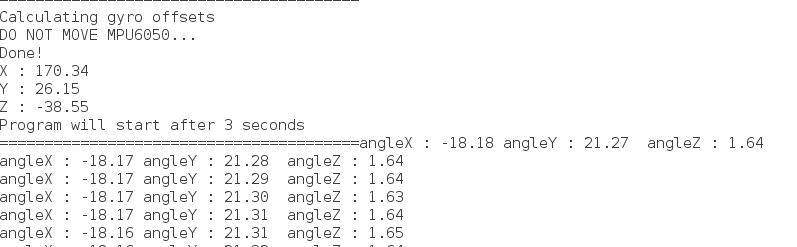
So after a few tests I realize that getting consistent reading is not as easy as I thought it would, there is a non negligible drift on the z value. There is probably some fine tuning necessary in the future in terms of which value = which side. but for now I only care about the x value since I want to know if the board is pointing left (x ~= -80) or right (x ~= 80)
Which translates to this code :
#include <SoftwareSerial.h>
#include <MPU6050_tockn.h>
#include <Wire.h>
MPU6050 mpu6050(Wire);
SoftwareSerial EEBlue(10, 11); // RX | TX
int pos = 0; // unset = 0, left = 1, right = 2

void setup()
{
  Serial.begin(9600); // Initialize the serial port and set the baud rate to 9600
  Serial.println("UNO is ready!");  // Print the string "UNO is ready!"
  Wire.begin();
  mpu6050.begin();
  // offsets that I previously calculated using mpu6050.calcGyroOffsets(true);
  mpu6050.setGyroOffsets(-1.58, 0.69, -1.71);
  EEBlue.begin(9600);
}


void loop() {

  mpu6050.update();
  float x = mpu6050.getAngleX();
  float y = mpu6050.getAngleY();

  if (x < -50)
  {
    if (pos <= 1)
    {
      EEBlue.write("right\n");
      pos = 2;
    }
  }
  else if (x > 50)
  {
    if (pos == 0 || pos == 2)
    {
      EEBlue.write("left\n");
      pos = 1;
    }

  }

  Serial.println(x);

  Serial.println(pos);
}
Pretty easy right ? Here’s a little demo of the whole system :
if that video didn’t work try this link
So now we have a system that can send data to a paired phone and detect orientation ! success ! Now all that’s left to do is to port that code to a production board, 3d print a cube, fit all of that inside, get the position data for each side (side 1 is x/y, side 2 is x1,y1 etc…) And we are good to go on the hardware side !
If you have experienced drift issues with the MPU6050 and know a good fix. I would be interested. Please consider subscribing to the mailing list to avoid missing any future episode of this serie 🙂